▛▀▖▗ ▌
▌ ▌▞▀▌▙▄▘▄ ▌▗▘▞▀▖
▚▄▌▚▄▌▌ ▌▐ ▛▚ ▛▀
▗▄▘▗▄▘▀▀ ▀▘▘ ▘▝▀▘
Logs and progress updates
=========================
> DATE: 2026-06-24
For the past few weeks I have been putting off writing a new log here, thinking there wasn't enough meaningful progress to note. Yet it's been 10 weeks since the previous one and I now have three logs' worth of progress to share.
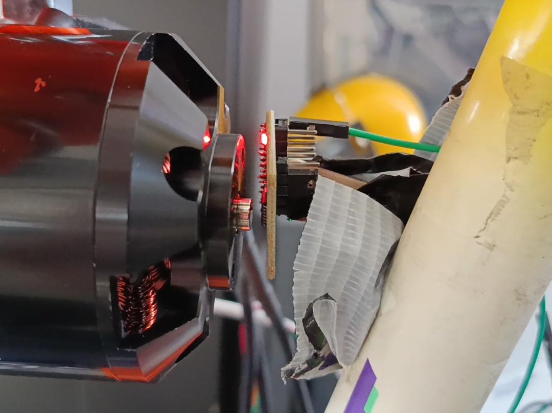
Shortly after the previous log I got the Hall effect sensor I needed. Mounting it to the bike frame was fairly easy given the amount of hot glue and free time I had, despite its fairly harsh requirement - to be exactly within 2-3 mm of the magnet and directly above its center. Despite that, it soon started to read proper data from the magnet (held onto the motor by its own magnetism) and the VESC seemed to pick it up properly! Truthfully, this stage gave me a sense of optimism that was at best missing by that point given how long I felt I have been working on this project at that point compared to the progress I saw. So, I ran VESC Tool's FOC motor detection and angle calibration sequences, and the results were... perfectly whelming. Nothing at all had changed. The motor still had that annoying startup sequence from 0 RPM to full torque as often as it did before.
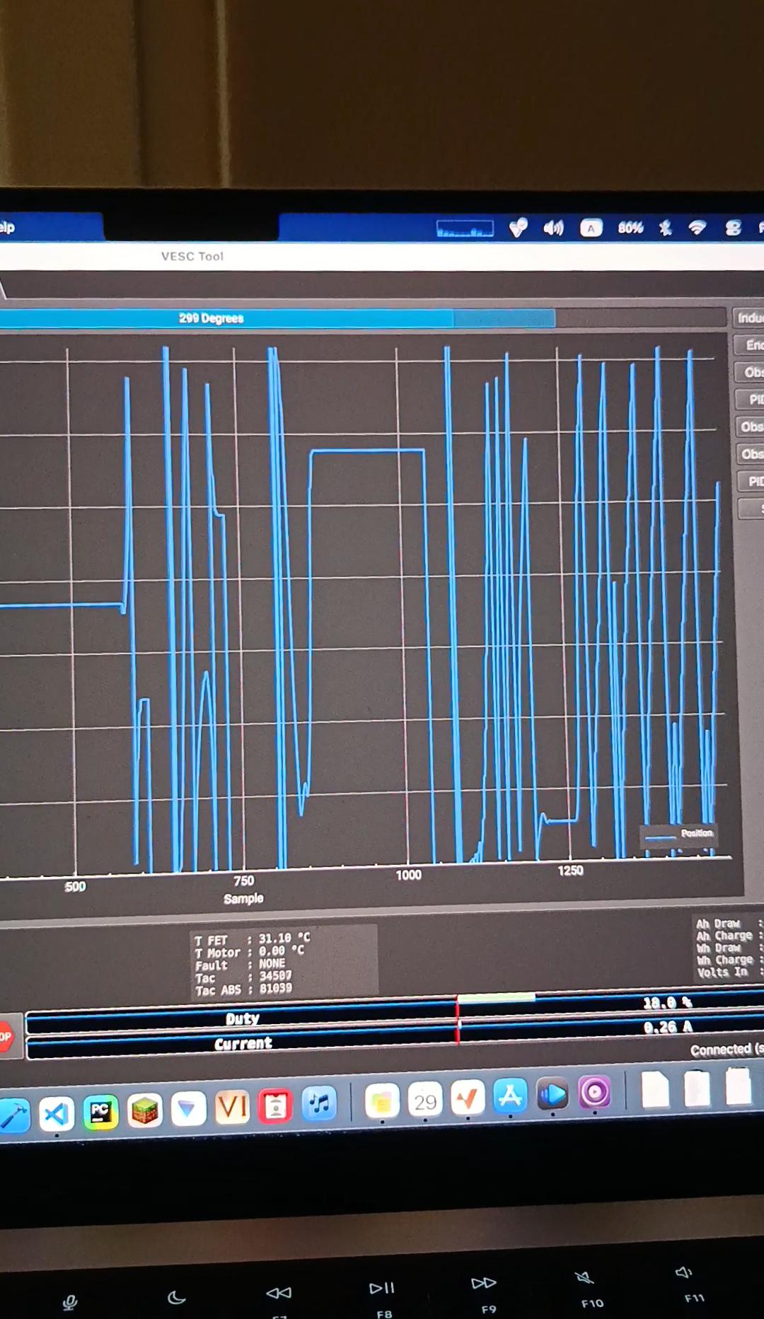
So I figured something wasn't working in the chain. VESC Tool's real time page showed that something was off with the angle. It was both inaccurate with manual rotations, and stopped reading at all past a certain speed.
The first one was resolved by a few hours of trying different wiring configurations from the magnet sensor's 19 wires into the VESC's 3. For that one, the correct wiring was "just" taking the sensor's ABI, wiring it to the VESC in the opposite order as is supposed to be correct, and disconnecting the I pin.
I really did try to find the cause of the second problem, readings stopping after a bit.
I originally thought it was a matter of electromagnetic interference. So I tried looping a GND wire around the data wires and having them orthogonal to the power wires, then to just physically separate them by 50 cm or so, yet this persisted regardless. I then tried spinning the motor fast enough by hand (via the pulley, it had to be pretty fast), but still the same result. Also when I spun it up with 0.5 A.
So maybe the magnet was the problem? Like, spinning it up fast enough just somehow caused it to slow down enough or somehow hover a bit? Evidently that wasn't it after I hot glued the magnet to the motor and this persisted. Thought I was killing two birds with one stone by also making it easier to align with the sensor.
So I still don't know what it was. Theoretically, it shouldn't even matter. The startup sequence reads fine, and that's exclusively where the stutter shows up. But I have been carrying the sunk cost of the original BLDC for too long.
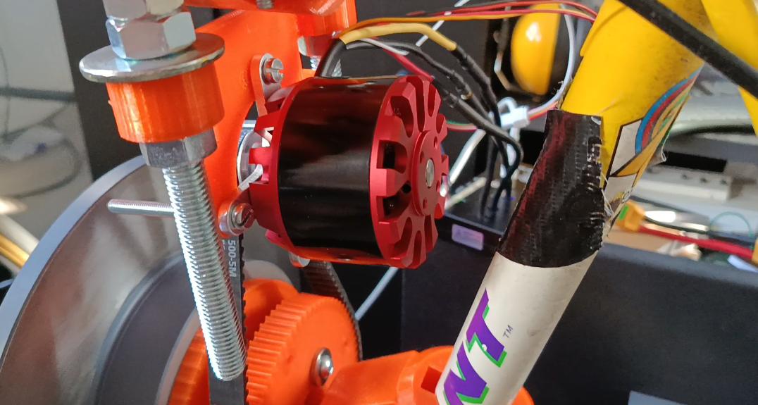
In all this time, I ordered and received a new BLDC motor, one I found that both fits all existing hardware and comes sensored, with a close-enough motor constant.
The new motor is one of the first results online when searching for a 6354 outrunner BLDC, made of straight Chinesium. It is 180 KV and came in an entire cardboard box with no mount or screws for said mount, nor any sort of protective foam in the pack. Yet it works and the old motor's screws fit perfectly! I had to take out its pins from its 5-pin header and rearrange them into a 6-pin header I had laying around so I could actually plug it into the VESC, though once I did it worked perfectly. I am willing to blame Flipsky for this rather than the motor's great manufacturer, ShenZhen MiaoZheng Technology Co., Ltd.
This changes the math slightly - 180 KV with the same 6S battery means that I will get around 38% more torque (250/180) but that we will reach saturation faster. This is not necessarily a bad thing, just something I need to keep in mind. The new motor has a larger shaft than the previous one, but I managed to find a pulley with the same tooth count, so the transmission ratio is still the same 15 to 72 teeth.
I actually already rebuilt the bike with it, and it actually works perfectly now, no stutter at all with torque at 0 RPM!
I have been trying to implement a faux-LQR controller on it since installing it. I know that whatever equipment I have available is not nearly good enough to get good inputs for state-space equations. Any value for center of mass height and for the flywheel inertia are practically guesses. It seems that the most common test for a bike's center of mass is the hang test (hanging it twice from two different points and seeing their lines' overlap), but it seems that is much easier said than done when I don't have somewhere to hang it.
But what I do know is that an LQR controller here would act as a "PwD" controller - getting the proportional and derivative to the lean angle, and the flywheel's angular velocity (w). So U = k_p*theta + k_d*theta' - k*w. The angular velocity is read directly by an ESP32 (which controls the whole operation) from the VESC, and it reads theta from a GY-521 sensor which goes through a Kalman filter (also on the ESP32). The 16-year-old sensor should be retired someday... but today is not that day. It has been incredibly easy to work with, and gave me absolutely no problems. I do also have a much more modern Bosch BMI160 I could use, but truthfully I really don't like the process of soldering headers onto the PCB, so I am putting it off for as long as the current sensor works well enough.
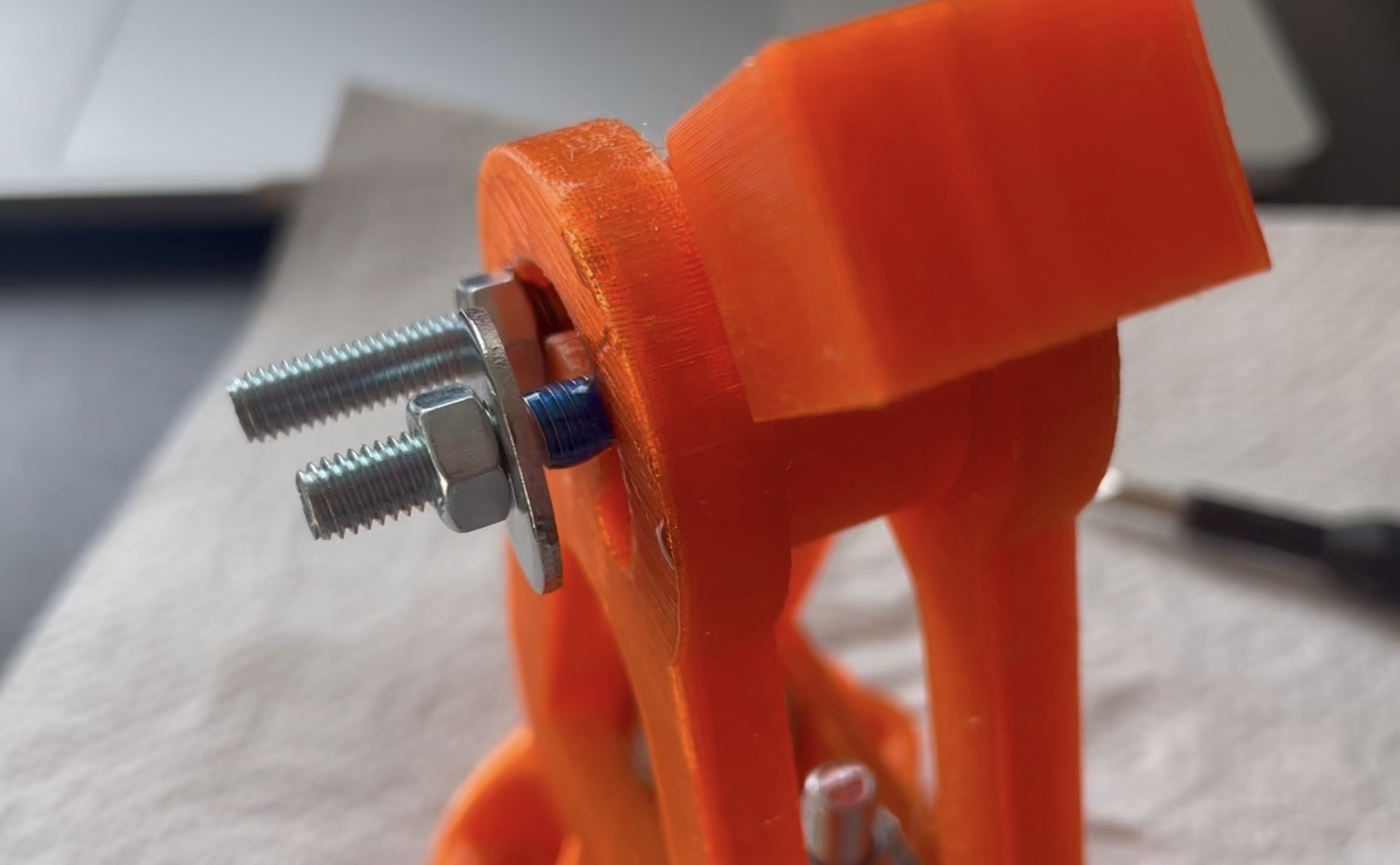
I have been tuning it, and actually got really good preliminary results! I have managed to get the bike to oscillate back and forth around being upright for a few seconds before oscillating out of control. This was the first time I actually saw "real" potential for the project, and it really did make me incredibly happy to see. This essentially shows there is potential in this, and I am down to creating a controller. And that is also where I am now, tuning a controller by hand. Disappointingly, all the PwD controller needed to reach this point was0 a k_p value of 4, k_d of 1, and not even using k_w (these are multiplied by the angle in degrees not radians, so the derivative shoots up super quick). But this oscillated really violently, especially over time. I initially attributed that to flimsy data from the GY-521 and tried adding a low-pass filter, which partially helped, but generally just made this basic balancing much harder. I have not yet gotten it to work with a low-pass filter implemented. I suspect the actual problem is not just flimsy data for the sake of it, but something I have been trying not to address - vibrations in the frame. That is a problem I don't really know how to get traction on. As far as I can tell, the flywheel no longer has any runout, at least not visibly. There seems to be no slack in the pulley transmission, and it seems that the frame only really starts to vibrate violently after reaching a certain RPM (rather than when rapidly switching motor direction). What I do notice is that this vibration seems to correlate with the shaft's free end bouncing up and down within the gap it is inserted into. The initial thinking was to not over-constrain its degrees of freedom, and thus the shaft currently fits into two holes and constrained axially by two nuts on both sides of one of the gaps, and is completely free on the other to move axially. Yet evidently also up and down.
The system is incredibly sluggish now. I have two candidate reasons for this, both of which are fairly "bureaucratic":
1. The low-pass filter introduces too much phase lag, something that is fairly easy to fix but I have not gotten around to yet,
2. The script loop, despite trying to act at 100 Hz, experiences too much delay by trying to read the flywheel's velocity from the VESC.
But progress is fairly slow at the moment. I am currently wrapping up the fourth quartile of the second year of my degree, this one is actually about almost exactly what I am trying to do with this bike (though smaller and more hand-held). It will be uniquely braindead to fail my exams about control systems and dynamics because I have been building a robot utilizing those principles, and so I have been spending much of my time lately studying for those two exams, so I have been prioritizing studying over the project.
We also actually have a project in this quartile where we design and build a machine that is meant to track a reference function precisely, then tune a PID loop for it (though it is a linear system unlike the bike). That is to say, I should be gaining experience ostensibly relevant for this project; unfortunately most of that experience seems to lie within the fields of managing frustration about software idiosyncracies and rationalizing engineering recisions in retrospect.
[IMAGE]: The Hall effect sensor, taped to the bike frame.
[IMAGE]: The weird sensor readings on VESC Tool (the flat lines happen when the motor spins too fast, not when it stops).
[IMAGE]: The new motor :)
[VIDEO]: Very early tuning (this is before it could balance and oscillate).
[VIDEO]: The uni project. Work in progress.
-----------------------------------------
> DATE: 2026-04-16
It's been some time! I am writing again now as I think I have achieved the next big milestone in making this function, proving actual authority from the mechanical setup, i.e. having the device demonstrate it can actually tip the bike over.
I completely avoided the printing problems from the last log by just printing at my university.
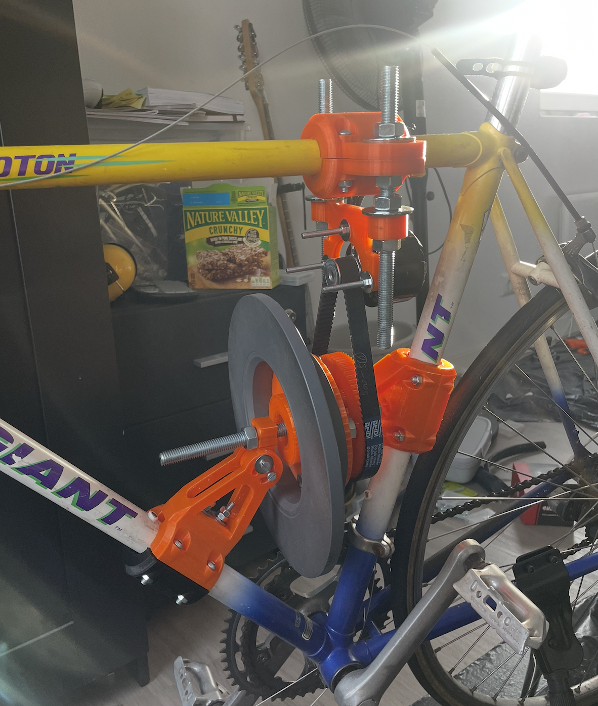
As of right now, I can control the motor manually via VESC Tool which drives the flywheel as intended. The structure seems to be able to handle everything well: vibrations no longer tear apart the frame over time (more on that in a bit), I am able to tension the timing belt between the motor and flywheel pulley well while simultaneously not over-constraining either (which was practically mandatory as I could not measure the bike accurately enough to have a perfect struture printed), and importantly, there is almost no backlash from the motor to the flywheel.
The electronic side seems to be faring well for now. None of my shoddy solder joints are acting up at the current currents I've tested (for now 60 A burst and sustained 40 A) and are surprisingly all cold after testing.
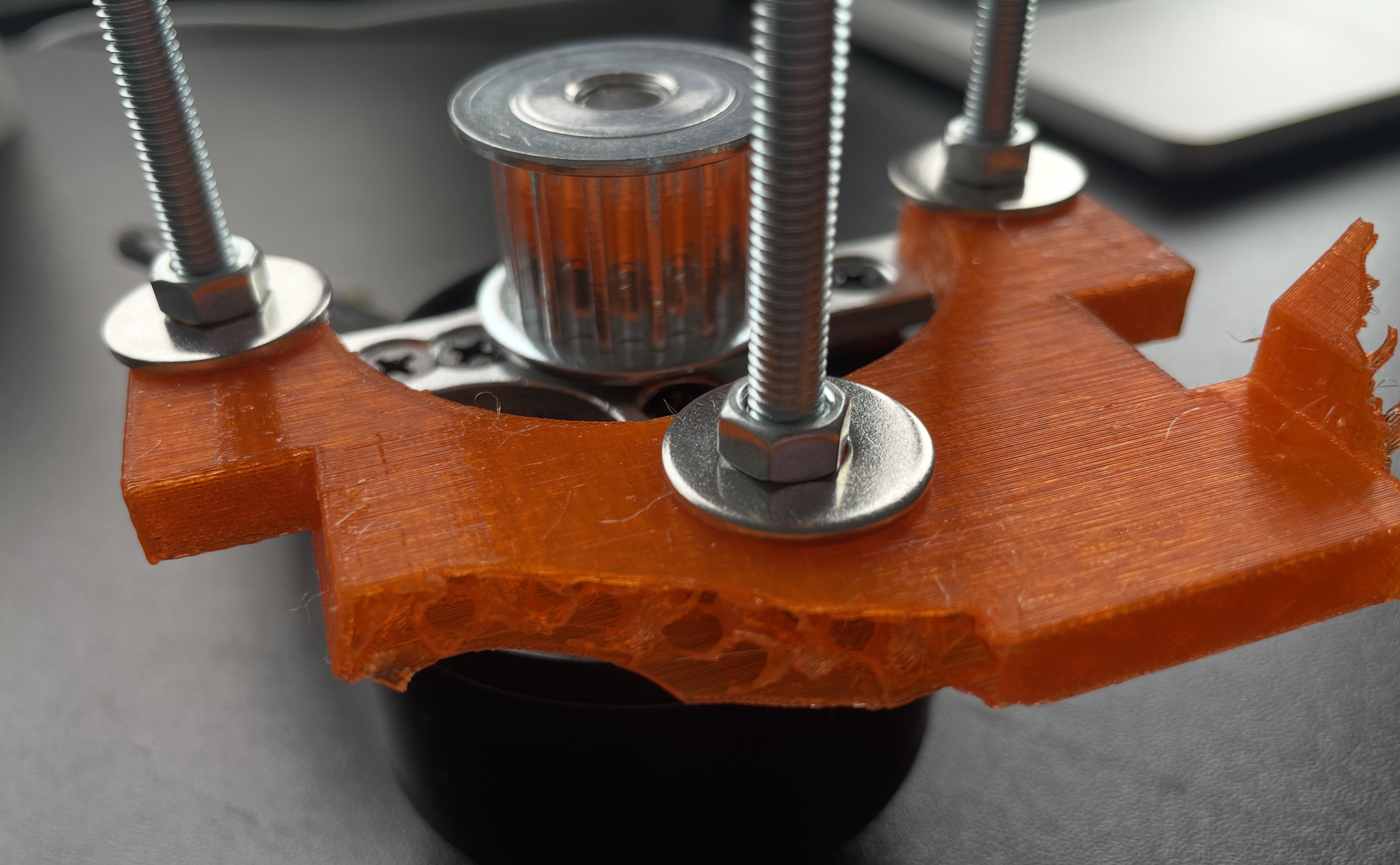
I also had a lot of structure problems with the initial version, as many parts were held together by nuts and bolts which are apparently easily undone by the flywheel spinning. Instead of redesigning I opted to first attempt address the issue directly by rebuilding the whole structure but also dumping half a container of blue threadlocker into it, a solution that actually seems to have worked extremely well!
One of the last things I have to square off before I can start implementing LQR is to fix how the system currently handles a cold startup of the motor. As it's sensorless, the VESC has no clue about the rotor position and thus has to play a small startup sequence before actually sending the peak current. This is because the speed controller relies on back EMF from the motor to determine its exact position and that is nonexistent at 0 RPM. In practice this causes a stutter with the motor that lasts around a second anytime I command it to apply torque. This thankfully seems to be an easy problem to solve, as the VESC I have bought has support for adding a hall sensor, and the motor has a free side where I can mount a magnet. The only problem for now seems to be mounting the actual sensor (I have bought an AS5047P) and it has to be around 3 mm away from the magnet at all times, making it ostensibly super easy to accidentally move too far away or to have it shredded by a super fast motor. Though once I have that, I think I can just get to writing the control system.
Finally, something that made me extremely happy is that it seems the setup has more than enough to balance the bike on power alone! I attached a video at the bottom of this log showing some initial testing. The bike swayed to the opposite direction even when this video only had a burst current of 40 A.
A brief chronological overview of the progress needed to get to this point over the last few weeks:
- Gave up on solving the 3D printer issue
- Printed all structure parts at my uni from PETG
- Buy all remaining metallic hardware (mostly nuts and bolts) and assemble everything
- Had to fix a lot of unexpected wobble (runout) with the whole flywheel hub assembly
- Connected everything and tested increasing currents
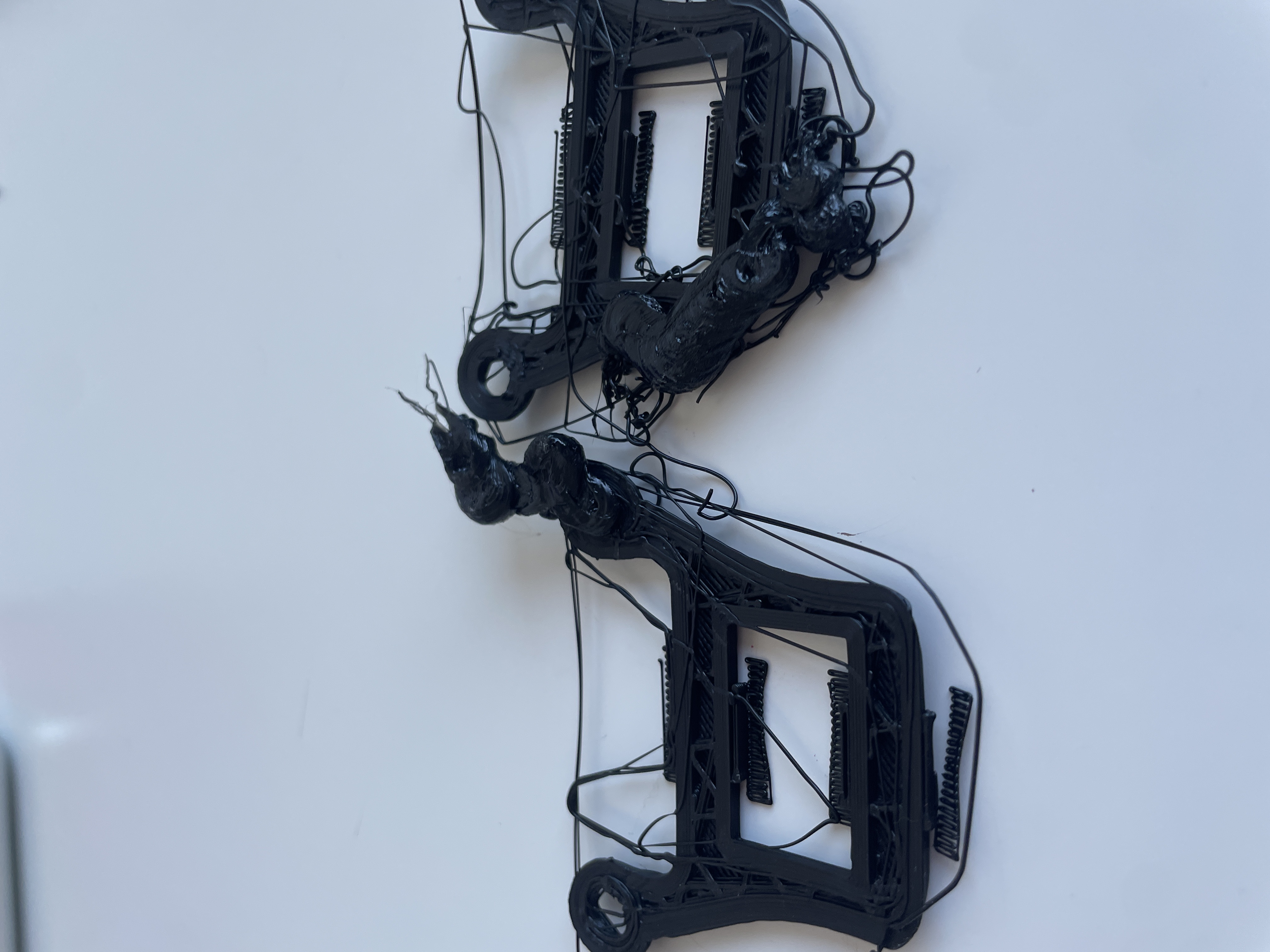
- Had a 3D printed part blow up in my face (literally) when trying to push 30 amps
- Neglected the project for 3 weeks because of uni exams
- Made a few changes to the part that blew up and that whole substructure, printed those
- Rebuilt the structure with the threadlocker
- Now writing this, waiting for parts to arrive to address the back EMF problem
- Hopefully very soon, use the parts to make the motor operable at 0 RPM and write the LQR loop
[IMAGE]: The structure on the bike.
[IMAGE]: After concluding rapid unscheduled disassembly on the part that holds the motor.
[IMAGE]: Using (too much?) threadlocker to fix the vibration issue.
-----------------------------------------
> DATE: 2026-03-02
The bed adhesion problem from the last log seems to have mostly gone away. It is now replaced by a clogged nozzle problem, on which I am going to try a cold pull tomorrow. My roll of PETG has also arrived today.
I have also made significant progress on the "flywheel problem" which I did not mention here yet. Essentially, I realized it might be problematic to spin a homemade 4 kg ring of solid steel at 1150 RPM, mounted to shoddy 3D printed mounts. Because it is applied a moment and not much force, it shouldn't actually pose a big risk if it spins well. Unfortunately, since I am the one making it, it spinning well is a generous assumption. Just a small imbalance in any direction could cause it to begin vibrating and inevitably shred through any 3D printed mounts.
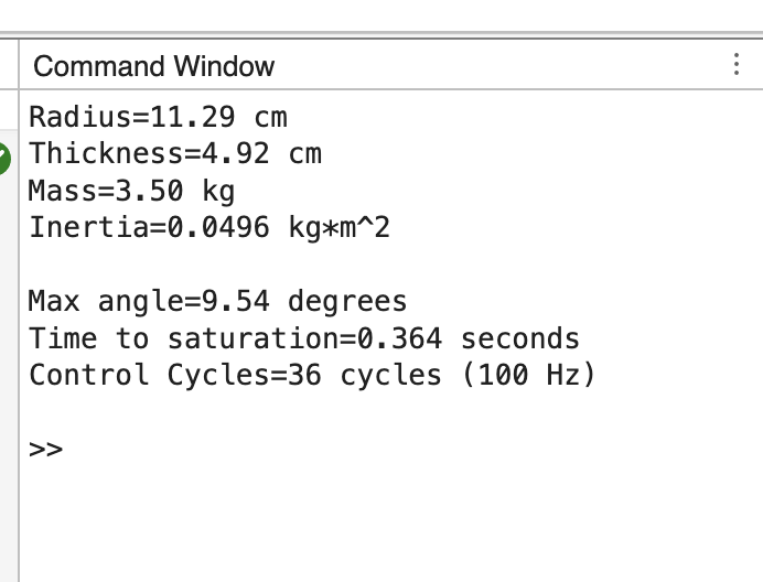
I have found the ideal flywheel specifications using a simple MATLAB script, optimizing for the highest recovery angle while minimizing flywheel radius and mass. Technically, from a moment balance, the only thing that matters for maximum recoverable angle is the torque applied by the motor. With 250 KV and a 1:4.8 pulley transmission, this torque can reach up to 18.3 Nm at 100 A. The flywheel is important because its moment of inertia is what allows the motor to apply this torque for a longer time before the motor reaches its maximum RPM (5550). With the value of 0.05 kg*m^2, the ideal flywheel configuration (Image 1) allows the bicycle to recover from an angle of 9.54 degrees, and has 0.36 seconds to act before reaching saturation. This time will definitely pose a challenge later on, especially with any delay that might occur throughout the system - it is non-trivial when considering the whole system, bike tilt -> IMU -> Kalman filter (ESP32) -> VESC -> Motor -> pulley (with any backlash) -> flywheel. However, an ESP32 can definitely handle a 100 Hz control loop, so 36 control cycles should still give the system a fair chance to recover. Plus, a recovery of 9.5 degrees would rarely be needed if starting from an upright position as any tilt will be corrected long before it reaches that amount of tilt.
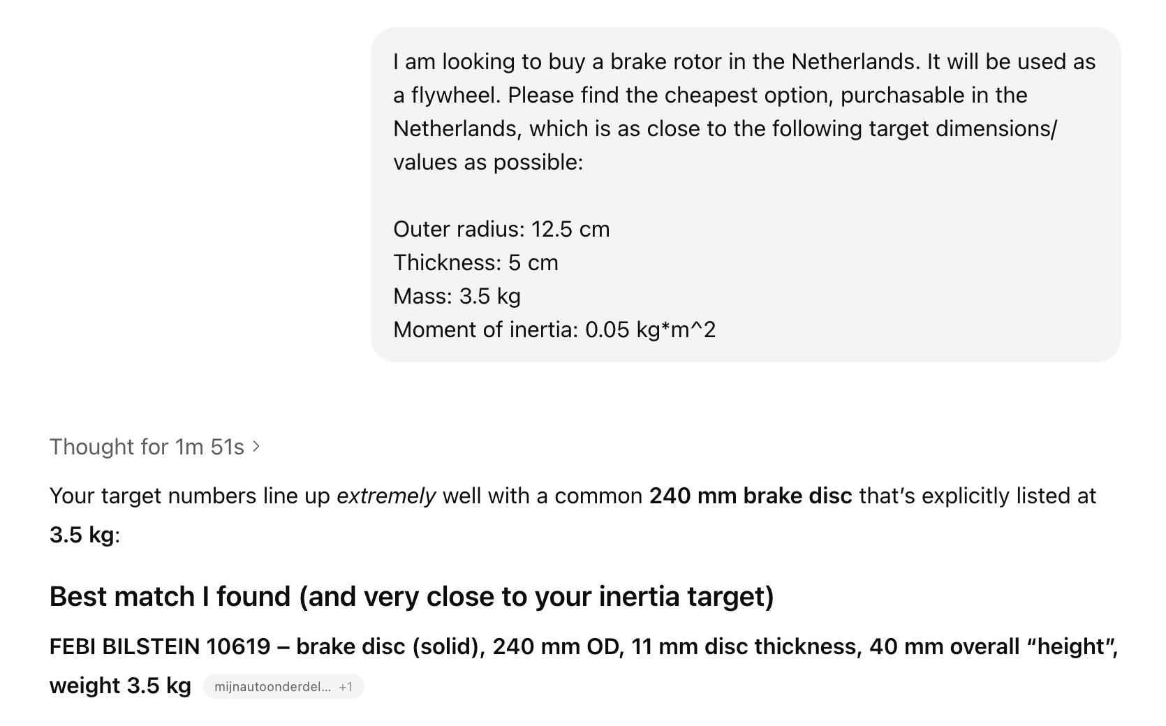
Anyway, the problem of fabricating a very precise metal disk has been entirely solved by just buying one on Amazon. Specifically, I realized I could use a car brake rotor which are meant to handle rotation of speeds higher than I require, and almost always have a perfect shape for maximizing moment of inertia. I had ChatGPT find one that matches my requirements and I will soon order it. It only has one major disadvantage for now: It has a "hat" shape, meaning the heavy outer ring is not aligned with the mounting holes. This can probably be fixed with a good mount, so this option still seems like the best one for a flywheel.
[IMAGE]: The ideal flywheel.
[IMAGE]: "Parts sourcing".
-----------------------------------------
> DATE: 2026-02-28
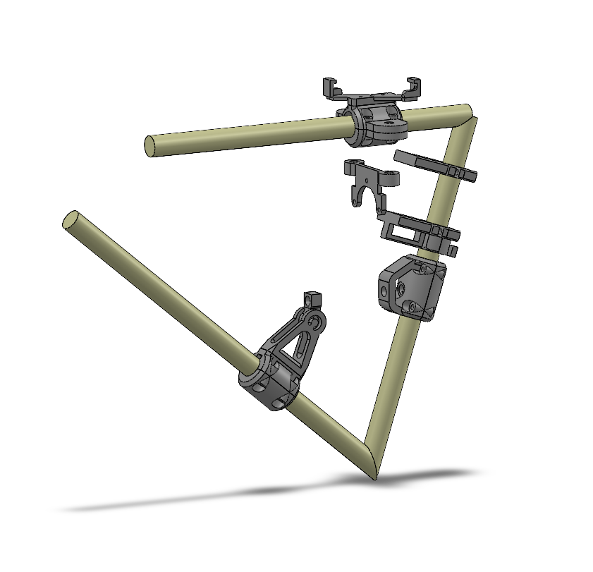
Finished the first full version of the structure holding everything together. This is the version I will initially print with PLA and PETG. The goal here isn't to use this in the final bicycle (though that would be nice), but to essentially push it to its limits to see what parts need to be reiterated upon and what parts can actually be used in the final version.
There are quite a few "interesting" design choices made and honestly I am not too happy with them. They are "interesting" because they have a lot of complexity that is often necessary - a few exampls:
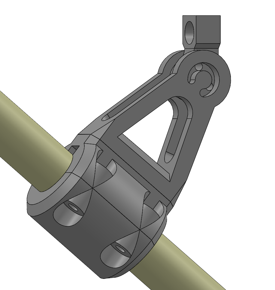
- (Image 1) I am having quite a bit of difficulty actually measuring the angle of the longest bike tube, and my previous attempt to mount an end of the flywheel shaft to a fixed piece has failed. I am therefore trying a shaft mount with an adjustable angle for now, but this ~could~ introduce a lot of stress to a few small parts, but it may also not, as the shaft should (theoretically) not actually experience that much force - it should mainly come from the flywheel's mass and be offset by the pulley tension (which is in the opposite direction).
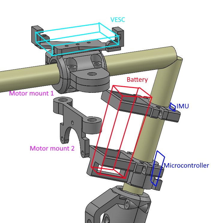
- (Image 2) I have opted to try mounting all the electronics at the top despite the fact that this will increase the center of height and make angle recovery harder. This is due to a practical reason, that at the currents I am anticipating to need, longer wires that stretch from the bottom to the top of the bike could literally melt. Also something about the LiPo battery dropping from that height and making this project into a self-balancing IED. A benefit here is that all other wires (IMU -> ESP32 -> VESC) are shorter as a consequence (the IMU should be as high as possible on the bicycle to measure the angle as accurately as possible, so it's also at the top) and I am dealing with an application so sensitive that having longer wires could measurably introduce lag to the control system and make it significantly harder to operate.
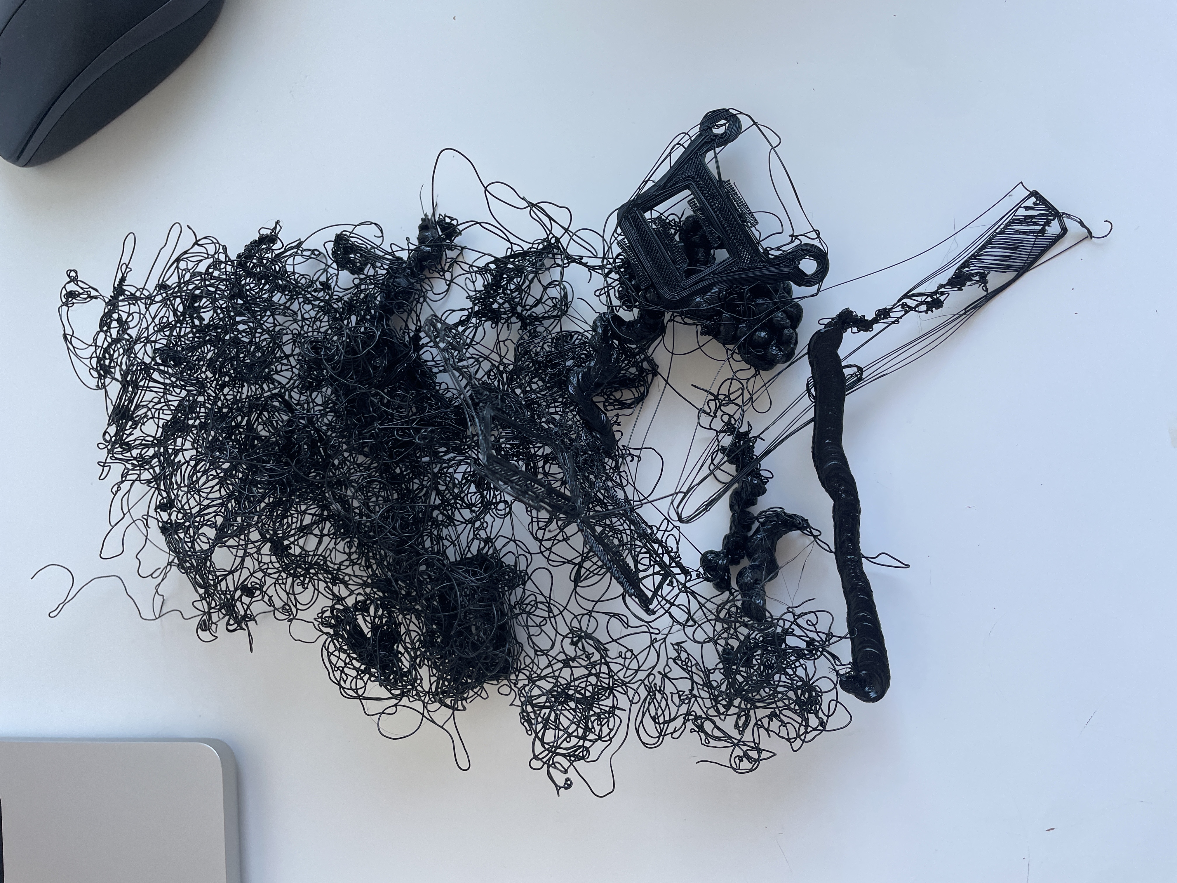
My yee yee ass 3D printer also seems to have lately been hyperfocused on ragebaiting me, with every single (PLA) print I attempt failing due to one of two reasons. At first, it seems that prints' lower solid layers were successful and they only detached from the base when starting infill. This is probably becuase I tried experimenting with one of the "ideal" infill patterns, Cubic on PrusaSlicer, which has intersecting paths in layers.
After that, I tried switching to Gyroid (which should be close to isotropic) and doesn't have this, but I am now seeing bed adhesion problems from the first layer despite leveling it. I will try another print later today with Gyroid after cleaning the bed and leveling it again.
[IMAGE]: Electronics "mounts" (questionable efficacy).
[IMAGE]: Everything else.
[IMAGE]: The four so-called prints, courtesy of Creality.
[IMAGE]: The prints detached after starting the infill patterns.
-----------------------------------------
> DATE: 2026-02-22
Starting this log (and whole website) today. The current state of the project is:
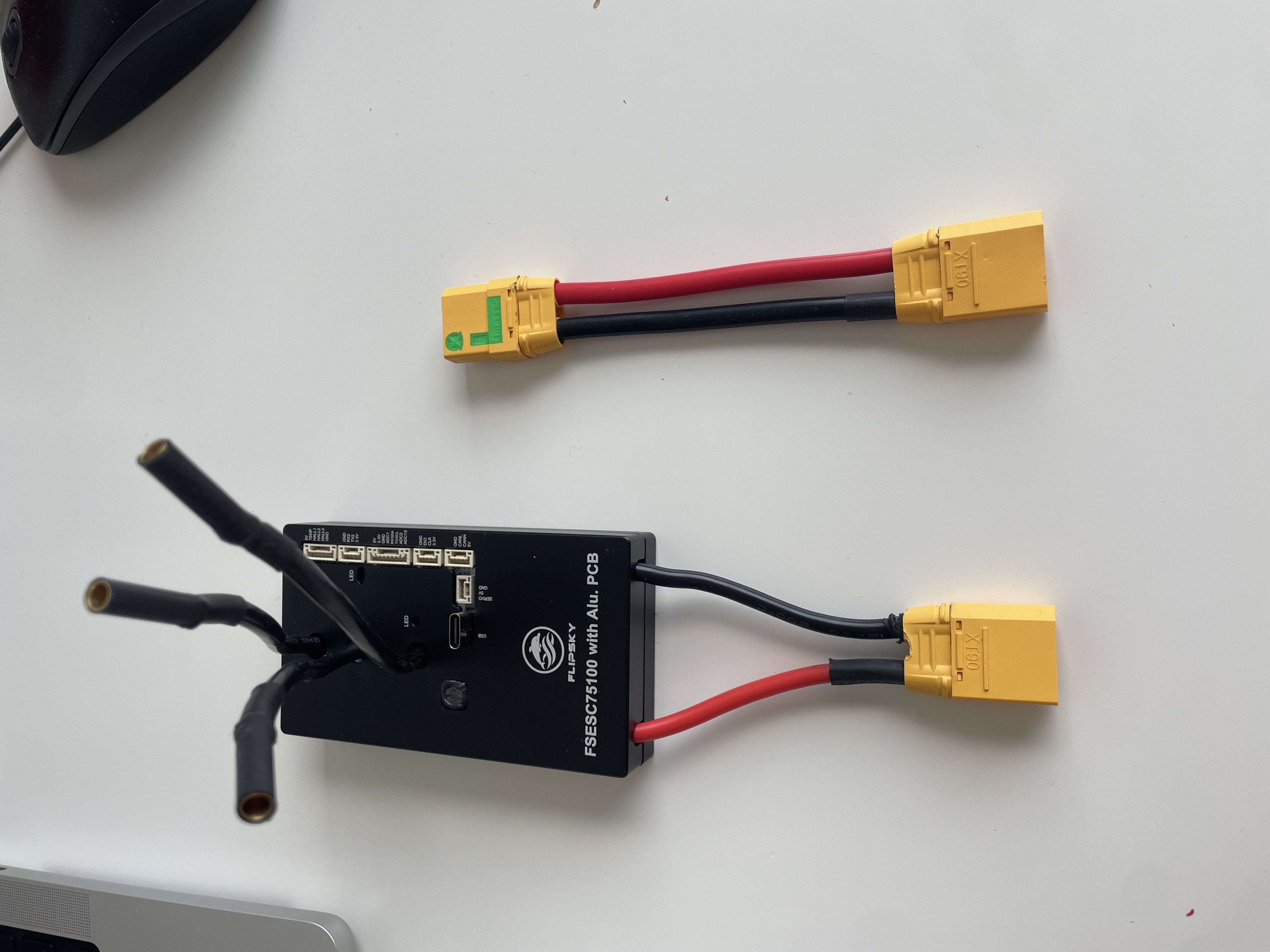
I have soldered everything together that needs to be soldered (Lipo -> XT-90S -> VESC -> BLDC motor). It seems to work fine for now, but I have only been able to test it at low currents (5 amps for now, theoretical limit is 100) because I do not have a mount and I do not want to hold an unloaded motor with 2.2 kW of power. I have also managed to connect an ESP32 to the VESC which is now able to read from it and write commands to it using the VescUart library.
The structure meant to hold everything together is technically ready to print in CAD, though the goal here is really to just break it as soon as possible so I can reiterate on it.
For context, the parts I am currently using are:
Control: ESP32
VESC: Flipsky 75100
Motor: Surpass Hobby C6354 BLDC (250 KV)
Battery: Spektrum G2 6S 4000mAh 50C LiPo
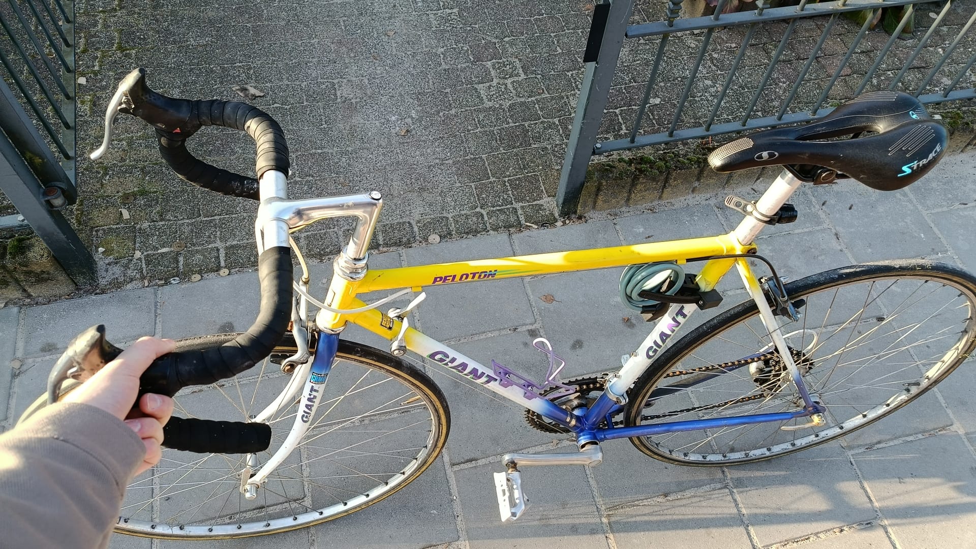
Bicycle: Giant Peloton (unknown model)
As for the physical structure I am planning to 3D print as much as possible, most likely with PETG (at the moment). I will try to lathe the reaction wheel into existence but this strongly depends on whether my uni will allow me to use their equipment. If not, I will order it as laser cut parts but this would be fairly expensive.
[IMAGE]: Figuratively picking up the bicycle.
[IMAGE]: Shoddy connections... I soldered the XT-90, XT-90S's, and the 3 motor leads.
-----------------------------------------